Setup WI-Fi
Setup in the EcoMonitor app
Wi-Fi
Step-by-step setup process for connecting EcoMonitor to a wireless network and then installing it in the electricity meter. The documentation mainly covers the WiFi version, but the device communicating over LTE-M will follow the same step 1, and then the process will be slightly different from the setup of the Wi-Fi device.
Before starting the setup, the user must have received an EcoMonitor device with the included USB cable (EcoMonitor WiFi) and network cable (EcoMonitor WiFi, LTE-M), the app must be downloaded, and ideally, the HAN port should be opened (to be ordered from the user's electricity supplier).
Ideally, the user should perform the setup near the circuit breaker panel to emulate the signal conditions where the device will end up. Alternatively, we recommend considering this factor when choosing a wireless network.
Setup - step 1
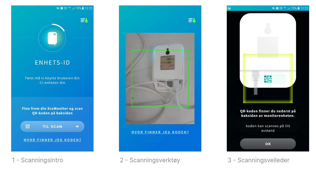
The user will here establish ownership of an EcoMonitor device, which is done by scanning a QR code on the back of the device.
The first screenshot (1) prepares the user for scanning the QR code; provides navigation to the actual scanning (2); and has a helpful link to a scanning guide (3). This link is also available on the actual scanning screen (2).
Possible discrepancies:
- Scanning may not be completed if the QR code is out of focus (this often happens when attempting to scan very closely) or if something obstructs a clear view of the code (e.g., cable ends on the sides).
- The user might scan the wrong QR code:
- A completely different QR code (which will result in an error message).
- The QR code on the cardboard box in which the device was delivered (this will give an error message; this QR code is used in our production and logistics and does not match the one on the actual EcoMonitor device).
- The user scans a device that is already associated with another user. This will give an error message, but it can only be resolved by removing the previous ownership, which is done by us upon request through support@harktech.no.
Setup - step 2
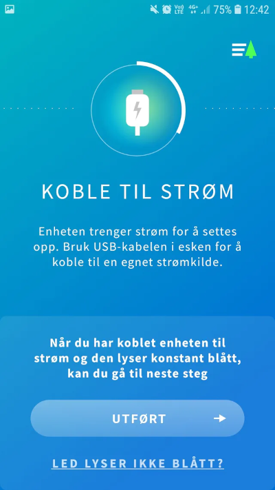
The EcoMonitor device must be connected to a suitable power source using the supplied USB cable. USB outputs on a computer or the plug module of a mobile charger are typically adequate.
As shown in screenshot 4, the natural outcome of a stable power supply is that stable blue LED light on the EcoMonitor device. If this condition is met, the user can proceed by clicking "completed."
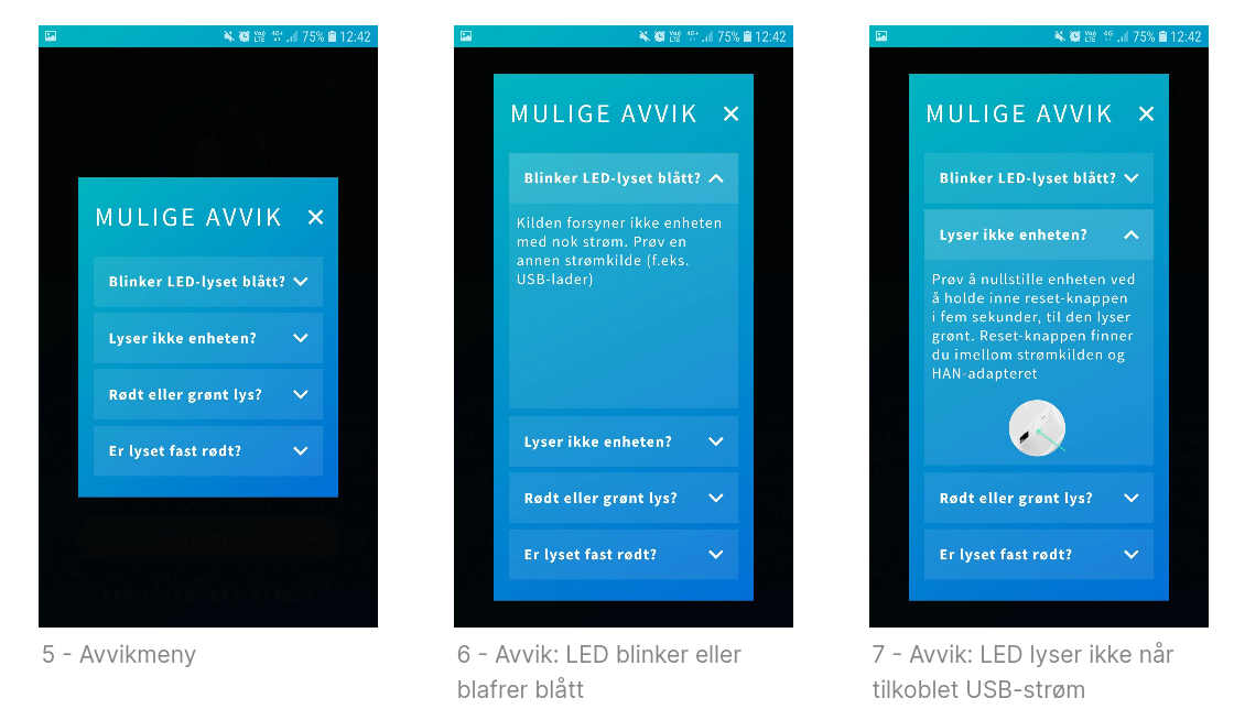
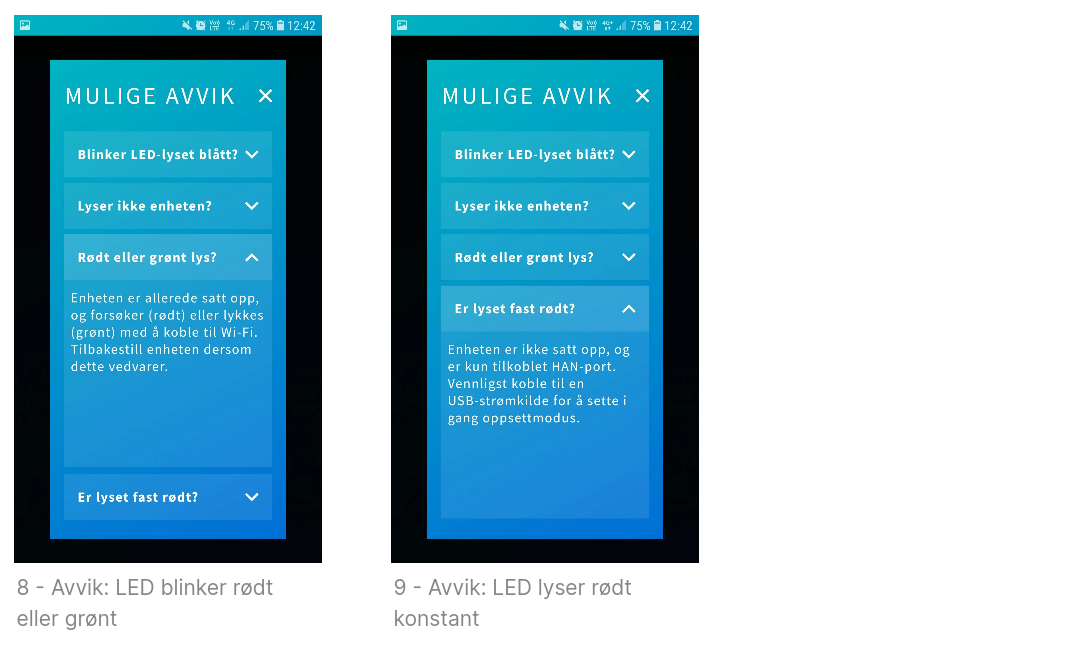
Possible discrepancies The LED light is not always necessarily blue, as one might expect, so we have handled some different deviation scenarios for this in the app. Screenshots 5-9 demonstrate scenarios of unstable light, no light (connected to power during setup), and instances of red and green light. These have different error handling, which is described in each subsection. Yellow LED light may also occur, but not in this step, so it will be covered in a later segment.
Setup - step 3
The app requires the correct formal permissions to be approved and enabled by the user. By clicking on the buttons (10,11), the user will activate their respective dialog boxes (depending on the operating system) where permissions are granted. When activated, the buttons will turn green, and when all three buttons are active, the app will automatically navigate to the next step. This step may also appear later in the setup process if the user, for any reason, affects the conditions (e.g., turns off WiFi during setup).
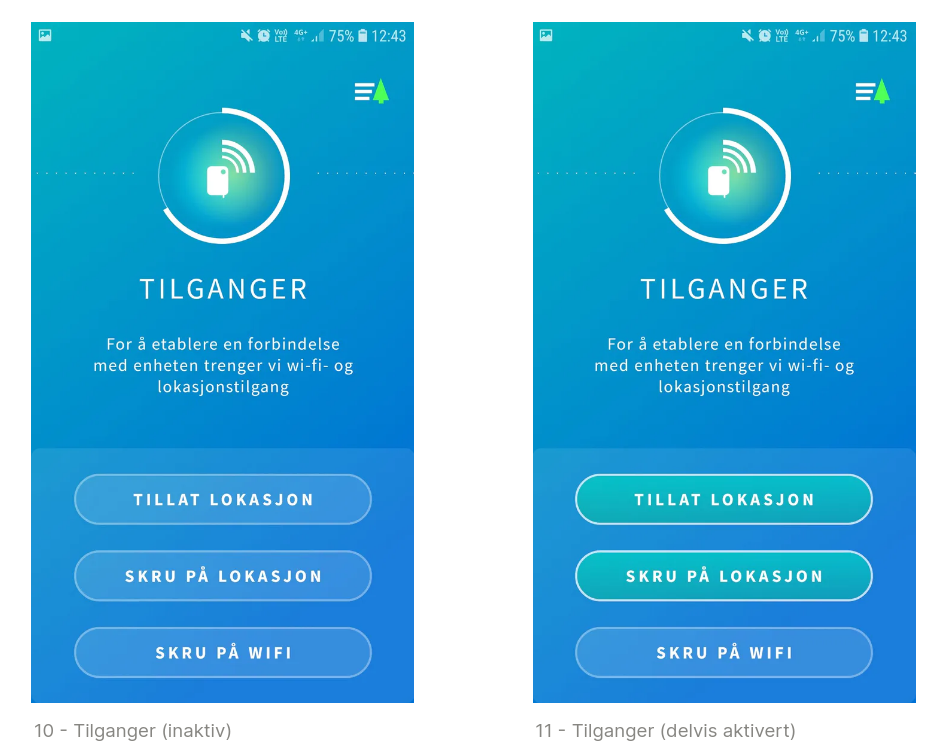
Possible discrepancies If the user accidentally denies permission when the dialog box appears, it will prevent the app from "asking for" this permission later. In this case, the user needs to go to the app permissions in the phone settings (outside the app) and manually grant/reset permissions.
Setup - step 4
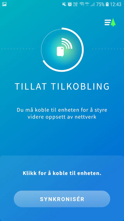
This step is simply an activation step where the phone connects to EcoMonitor through the wireless network set up by the device. This synchronizes the next setup steps with the device's internal WiFi settings.
Possible discrepancies: Synchronization will fail if EcoMonitor's own network goes down (e.g., due to power loss to the device) or if the phone is set to avoid networks not connected to the internet.
Setup - step 4.5
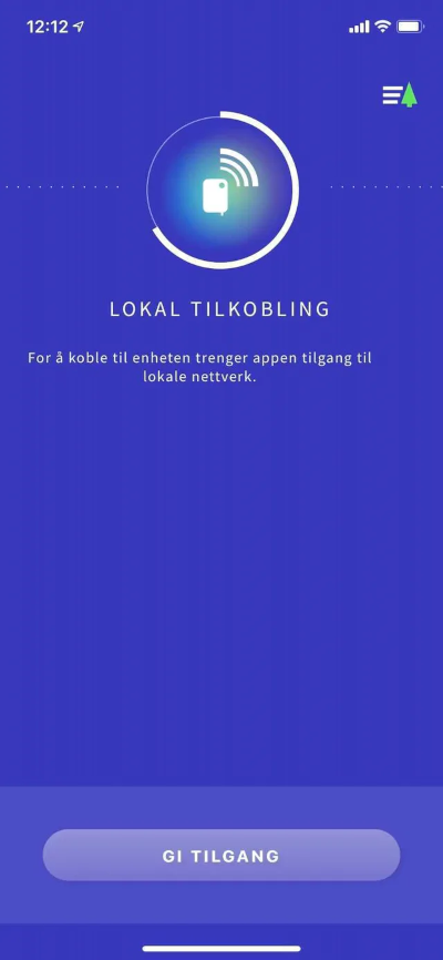
On iOS versions after v.14, an intermediate step is required to access and display local networks.
Setup - step 5
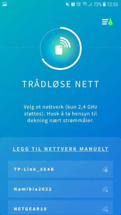
In this step, the app presents a list of wireless networks that EcoMonitor detects (13). The device does not support WiFi networks on the 5 GHz band and will therefore only pick up and display networks on the 2.4 GHz band. It is essential to look at the signal strength and choose the wireless network that provides the best conditions near the electricity meter/circuit breaker panel. Users can also add networks manually if they do not appear on the list (but meet the requirements) or if they are hidden networks.
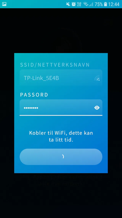
The app then opens the connection dialog box (14), where the network name is either given or added manually. Users must then enter the correct password (which can be shown/hidden with a click) and click the button to connect.
Possible discrepancies:
- Here, the user might accidentally enter the wrong password (or network name for manual connection), e.g., by having caps lock on.
- Navigating out of the app to retrieve login details from an external document or password service can, in rare cases, cause some issues. We recommend not leaving the app during the connection moment.
Setup - step 6
The final step appears when the login is successful and essentially marks the end of the process. Now, the device must be plugged into the HAN port of the electricity meter to retrieve power data. This message will appear as an info box until the power data starts coming in or when 120 minutes have passed. In the screenshot, we provide information about several important points for the next steps, including:
- The USB cable is no longer needed; EcoMonitor draws the power it needs through the HAN port via the network cable.
- The device should be placed or mounted outside the circuit breaker panel (which can block the signal completely or partially) and have the best possible coverage.
- A reminder about opening the HAN port.
- Explanation of the device's behavior when connected to an open HAN port. It will charge before sending data and blink yellow during this process until fully charged. The LED light will then blink red a few times while searching for the wireless network, then light up green when successful, and finally turn off completely for normal operation. The charging process usually takes only a few minutes but can take up to two hours in extreme cases (depending on the type of electricity meter).